

Please Leave Us A Message
Privacy statement: Your privacy is very important to Us. Our company promises not to disclose your personal information to any external company with out your explicit permission.

1 Electromagnetic interference (EMI) analysis
1.1 Concepts and approaches of electromagnetic interference
Electromagnetic interference is generated by sources of interference. It is an electromagnetic phenomenon that is external and internal and detrimental to useful signals. Interference interferes with the form of sensitive components, transmission lines, inductors, capacitors, space fields, etc. and acts in some form. The interference effects and phenomena are common and different in form, called conduction interference. It is divided into information transmission interference sources and electromagnetic noise conduction interference sources. The information transmission interference source refers to the interference of the useless information with the analog channel. The electromagnetic noise conduction interference source refers to the interference of the electromagnetic noise without any information to the frequency conversion system.
Conducted electromagnetic interference transmission channels can be divided into capacitive conduction coupling (or electric field coupling), resistance conduction coupling (or common impedance coupling), and inductive conduction coupling (or mutual inductance coupling). Capacitive conduction coupling refers to the electromagnetic conduction coupling between the interference source and the signal transmission line (including the printed circuit line) through the interconnection of the wires and the capacitance of the components. Resistive conduction coupling refers to the conducted electromagnetic coupling between the interference source and the signal transmission line (including the printed circuit line) through the current or voltage interlinking on the common impedance. Inductive conduction coupling is essentially magnetic field coupling.
1.2 Digital frequency conversion speed control system electromagnetic interference problem
These three kinds of conditions exist in the digital variable frequency speed control system. The performance of resistance conduction coupling and inductance conduction coupling is especially obvious, mainly the design of the reference ground, the design of the printed circuit board and the isolation of high and low voltage, and the analog interface circuit is vulnerable. The impact of the power circuit. The electromagnetic compatibility of DSP is mainly reflected in the electrical characteristics of the pin signal. Most of the input and output signals of DSP are digital signals, and most of the external interface circuits are digital circuits, including the power device IPM also works in the switching state. The whole system has obvious digital circuit characteristics, only the current feedback loop is an analog signal, through the DSP. The on-chip A/D converter converts the analog signal into a digital signal for processing, and then controls the PWM output to achieve closed-loop control. The performance of electromagnetic interference in this design is specifically analyzed as follows.
(1) The effect of transient pulse interference on digital circuits
The digital signal processor is based on a binary code. The high and low levels are used to represent the binary data, and the signal characteristics are described by various circuits to achieve the purpose of controlling the object. Transient pulse interference will seriously affect the data transmission and control state. Although it has strong anti-interference ability for the digital circuit itself, it is susceptible to high-energy pulse interference in high-frequency circuits, and the interference part appears in the clock generation. , bus data transmission, PWM control signals. The high-speed operation of the IGBT inside the IPM in the switching state will generate strong switching noise, which is brought into the low-voltage digital circuit through the coupling of ground, power, distributed, and distributed inductors, sometimes seriously interfering with the operation of the TMS320F240 digital signal processor. , manifested as out of control, program running and crashing.
(2) The influence of distributed inductance and capacitance on the signal
Based on the DSP control system design, the control part usually selects the TMS320F240EVM evaluation board. The design of the control circuit printed board is simplified. Only the circuit design and printed board of the IPM driver board should carefully analyze the distributed capacitance and distributed inductance between the signals. influences. However, it is important to consider the influence of the distributed inductance of the signal bus between the evaluation board and the driver board. It may cause signal delay and lengthen the rise and fall times of the PWM control signal, resulting in the upper and lower arms in the IPM module. The IGBTs are common, which will cause irreparable permanent damage to the IPM module.
(3) The impact of the power supply on the system
The power supply is a way for a variety of interference signals to affect the normal operation of the system, mainly with the following effects:
The internal resistance cannot be zero. Any interference signal of the common power supply can pass through the internal resistance of the power supply; the power grid is the channel through which external interference (such as lightning and electromagnetic emission) enters; the power load is disconnected and connected. A large impact will be formed on the power grid, and the impact of the inductive load will be more serious; the power supply itself will generate many interference signals, especially the switching noise generated by the high-speed switching of the IGBT.
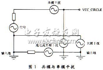
There are two forms of interference signals in the system, namely common mode and series mode interference signals. This is often used in digital systems to characterize the presence of interference effects, as shown in Figure 1. Serial mode interference, also known as normal interference, refers to the interference in series in the signal loop, which is generated by the mutual inductance of the transmission line, which is related to the frequency, which is commonly used for filtering and improving the sampling frequency to reduce. Common mode interference, also known as common mode interference, is the interference that occurs when the interference voltage is applied to both signal lines at the same time. Therefore, the line transmission structure is balanced to suppress common mode interference. In addition, the elimination of ground current can eliminate common mode interference by grounding or floating isolation (using a pulse transformer, choke or optocoupler to cut off the ground current).
2 hardware anti-jamming technology
2.1 Electromagnetic compatibility design of power system
The power system includes a low voltage auxiliary power supply and a main power supply. The low-voltage auxiliary power supply refers to the +5 V, earth 12 V, and 4 sets of +15 V isolated power supplies required by the DSP and its associated interface circuits. The main power supply refers to the AC/DC/AC power supply for motor drive and adjustable speed. It is isolated from the low voltage auxiliary power supply and is not shared. The anti-interference measures adopted by the power system are:
(1) The AC input to the grid should be supplemented with an EMI suppression filter, a low-pass filter consisting of a common-mode choke L, a capacitor C, and a resistor R. He can not only prevent the series mode and common mode interference signals of the power grid from entering the power supply, but also effectively prevent the interference generated by the system itself from entering the power grid, which is beneficial to environmental protection.
(2) When the IGBT is interrupted by a large current, the circuit is accompanied by surges of voltage and current. Due to the large du/dt and di/dt, the high-frequency components of the surge interference signal are high, and the IPM power input is high. A small-capacity high-frequency capacitor should be connected in parallel to eliminate parasitic oscillations.
(3) The power input/output power supply cable is connected by a twisted wire, which can reduce the radiation of the electromagnetic field generated by the current of the loop.
(4) Low voltage and high voltage are separated by transformer, optocoupler signal and ground line to block common mode interference. The suppression countermeasure is selected according to the difference of the duration Δt of the interference of the power output;
Δt>1 s belongs to overvoltage, undervoltage, and power failure. Suppressed by uninterruptible power supply (UPS) and Voltage regulation;
Δt>10 ms is a surge, sinking, and falling out interference. This type of interference voltage has a large amplitude and a fast change. It is not a burnt system or an oscillation. It requires a fast-responding surge absorber and a voltage transient suppression diode (TVS). ) to prevent;
Δt is microsecond, which is a spike voltage interference. Because the duration is short, the system will not burn out, but it can destroy the operation of the source program of the DSP, and the logic function is confused. The signal line should be away from the interference source and shielded;
Δt is nanosecond, which belongs to radio frequency interference. It is not serious to the DSP and digital signals. Generally, high-frequency decoupling capacitors can be added to the power input end of the IC.
Pump speed is generally slow down the problem. When the use of frequency control, the original design by the frequency of the state of the pump and motor operating parameters have undergone major...
Affected by the macroeconomic environment, China's inverter market in 2012 is not ideal. According to the company announced 2012 earnings, ABB Group sales in 2012 was about 3.7 billion yuan,...
[Asia pump network hearing] variable frequency constant pressure pump installed as required to ensure its normal operation. Next, Xiao Bian and everyone introduced DYWPX2 variable frequency pump...
Pump speed is generally slow down the problem. When the use of frequency control, the original design by the frequency of the state of the pump and motor operating parameters have undergone major...
Email to this supplier
Privacy statement: Your privacy is very important to Us. Our company promises not to disclose your personal information to any external company with out your explicit permission.
Fill in more information so that we can get in touch with you faster
Privacy statement: Your privacy is very important to Us. Our company promises not to disclose your personal information to any external company with out your explicit permission.